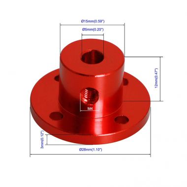
Description: Flange couplings are mainly used to connect the drive shafts between pumps and motors, transmit torque, compensate for minor misalignment, and achieve coaxial transmission of the pump unit. They consist of two flanged half-couplings and connecting bolts, and have a simple structure and high load-bearing capacity.
Materials
1. Main half-coupling: commonly used HT200 gray cast iron (for ordinary water pumps normal temperature conditions.
Low cost); 45# forged steel is used for medium and high pressure and heavy load applications; 304/316 stainless steel is selected for corrosive conditions.
Connecting bolts: Grade 8 carbon steel bolts for general working conditions; Grade 8 high-strength bolts for high vibration and heavy loads.
Stainless steel bolts for corrosive environments. Flange couplings are rigid couplings without elastic buffers and cannot absorb large vibrations.
Classifications
1. Standard flange coupling (YLD/YUL) consists of two half couplings with aligned stop surfaces and bolt-locked installation.
Available in reamed bolt type and standard bolt type.① Reamed hole bolts: Torque is transmitted by shearing of the bolt shank.
Resulting in high centering accuracy and making them for high-power pumps.② Ordinary bolts: Torque is transmitted by friction on the flange surface.
Making installation convenient and for small and medium power water pumps. Split flange coupling: radially split into two halves.
Remove the need to disassemble the motor and pump shaft making it convenient for maintenance and disassembly and is often used in large circulating pumps.
Coupling with intermediate sleeve flange: A short sleeve is added between the two flanges to facilitate the maintenance of the pump mechanical seal without moving the motor.
Commonly used in petrochemical and chemical pumps.s: Rigid flange couplings cannot compensate for large axial and radial deviations and have high requirements for installation alignment.
Poor alignment can easily cause rapid damage to pump bearings and seals.
Specifications Specifications are represented by shaft bore diameter.
Common shaft bore diameters for pump units are: φ20, φ24, φ28, φ32, φ38, φ42, φ48, φ55, φ60, φ65, φ70, φ75, φ85, φ95, and φ100mm.
Matching pump power ranges from small pumps of a few kilowatts to large centrifugal pumps of several hundred kilowatts.
Flange type: raised face flange with pilot locating; shaft bore connection is mostly keyway (flat key).
Scenarios for: Centrifugal pumps circulating pumps pipeline pumps sewage pumps process pumps and applications requiring stable operation.
Consistent speed and high-precision alignment. - Water supply and drainage pumping stations, circulating water systems, water treatment pumps.
- Petrochemical ambient temperature medium pumps; - Power plant auxiliary water pumps.
Not applicable: Conditions with large impact loads severe vibrations and large compensation requirements (elastic pins or diaphragm couplings should be used in these scenarios).
Points to 1. Strict alignment is required during installation; radial and axial misalignment shall be kept within the manufacturer-specified allowable tolerances.
Fitted bolts (reamed bolts) shall NOT be substituted with ordinary bolts; substitution will cause torque-transmission slip.
Gray cast iron shall not be adopted for high-temperature and heavy-impact operating conditions; forged steel is preferred.



 Contact Us